G Series High Voltage Power Supply

General Description
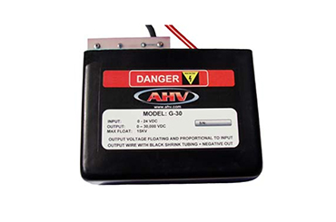
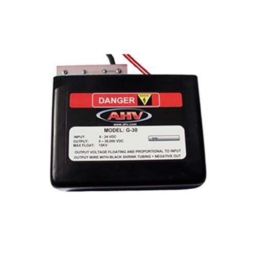
The G Series high voltage power supplies are designed to provide very high output voltages. They provide isolated outputs of up 50 kV with power levels to 20 Watts depending on model selected. The output voltage of the G power supply is directly proportional to the input voltage (0 – 24 VDC). The output ripple is typically less than 1% at full power load. The two output leads are floating and fully isolated from the input power leads by over 1T Ohm (@ 25 deg C). This permits either positive or negative polarity operation. All models are encapsulated in a thermosetting epoxy for high reliability. The G series are reverse input voltage and short circuit protected.
Features
Output proportional to Input
Encapsulated
5,000 VDC to 50,000 VDC available
20 Watts power (models under 30kV)
Metal case for low ripple: 1% Vpp

G Series Application Notes
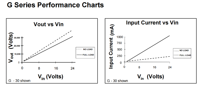
The G Series high voltage power supplies are driven by an input voltage of 1 to 24 VDC. The input current and output voltage as a function of input is shown in the above graphs. There are NO internal connections between the input and output pins. As can be seen from the above, the output voltage is approximately linear with respect to input except near the lower input voltage region. Here, the output drops off rapidly as the input voltage approaches zero with the absolute minimum input voltage needed for reliable starting being 0.9 VDC. As shown in Figure 1 below, the simple connection of a G unit to a DC source of voltage will provide a high voltage stepped-up output. The input AC bypass capacitor C1 is optional and is utilized to prevent switching spikes from riding back on the input power lines. Values of 0.1 uF to 10 uF are commonly used.
The output voltage of the G unit may be regulated by incorporating a simple op-amp circuit and linear control device such as an NPN transistor. Here, the output voltage is sensed and compared against an external reference control voltage. For single supply operation, the circuit of Figure 2 may be used for positive output regulation. A high voltage divider is made up of R5 and R6 to divide down the output to a value comparable with the control voltage. The resistor R5 is value is determined by power considerations. A good rule of thumb is to be 10% of the full output load. Too high a value may lead to output drift problems due to operational amplifier input bias current drift. The resistor R5 must be rated for the voltage that it is to step down. Simple high value carbon film resistors are usually avoided because their maximum voltage is limited to 300 VDC. Precision metal film resistors are more stable but also have limiting maximum voltages. It is possible to series several metal film resistors to build up the voltage rating of R5. Capacitor C4 likewise must be rated for the proper voltage. It serves to lower output ripple provide a feed-forward pole in the feedback loop for stability. Capacitor C5, the ground mirror capacitor serves as a lower end of the AC divider formed with C4 and prevents excessive voltage from being fed to the operational amplifier in the case of a shorted output.

