

General Description
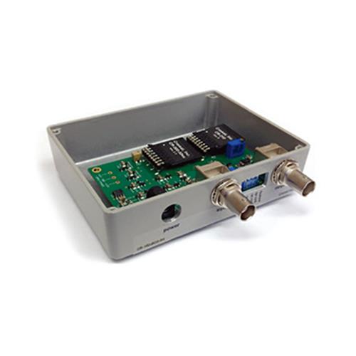
The CR-160-R8 is an evaluation board for the CR-200-X series of Gaussian shaping amplifier modules and CR-210-R0 baseline restorer (BLR) module. The CR-160-R8 makes it easy, providing BNC connectors for input and output, a wall mounted power supply, and sockets for the insertion of a CR-200-X shaping module and (optionally) a CR-210-R0 BLR module. To provide flexibility in the implementation of the CR-160-R8 within the users' instrumentation, the BNC connectors have been provided unassembled to the CR-160-R8 board. The CR-160-R8 has two switchable on-board wide-band amplifiers, each with a gain of 10. Combined with the CR-200-X gain of 10 (8 in the case of CR-200-50ns), this produces an overall gain continually adjustable between 0 to 1000. An inverted-polarity signal is available, as well as adjustments for pole-zero correction and DC offset.

Gain Adjustment
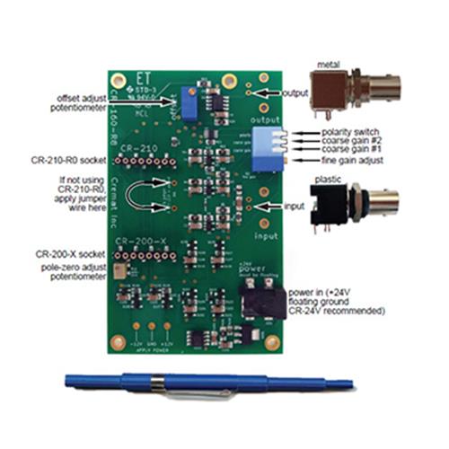
The fine gain of the on-board amplifier can be continuously adjusted using a small potentiometer placed between the input and output connectors (see diagram to the right).
The coarse gain may be adjusted by implementing one, both, or neither of the two separate amplification stages, each of which has a gain of 10 when 'on' (down). When 'off' (up), the gain of the stage is 1. Keep in mind that, in addition to the gain of the amplifiers on the CR-160-R8 evaluation board, the CR-200-X shaping amplifier module itself has a gain of 10,resulting in an overall gain to the input signal of anything in the range of 0 to 1000.
Installing the CR-200-X and CR-210-R0 Modules
Make sure that any module installed on the CR-160-R8 board is installed in correct direction! Installing the modules in the opposite direction will result in damage. Connect pin 1 of the modules (marked with a white dot on the label) to the side of the socket marked “1”.
Installing the BNC connectors
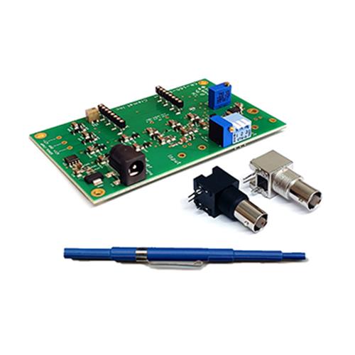
Two PC-mount BNC connectors are included but not installed. If you choose to install them,solder the plastic housing BNC connector to the ‘input’ position and the metal housing BNC connector to the ‘output’ position.

Signal Polarity
Signal polarity can be changed using one of the ‘piano style’ switches located between the input and output connectors. See the diagram for the precise location. Switch position of ‘on’ (down) inverts the signal from the input. If the CR-210-R0 baseline restoration module is being used, the CR-160-R8 output pulses must be positive for the baseline restoration circuit to operate properly. The polarity switch should be used in this case to insure that the output pulse polarity is in fact positive.
Applying Power
The CR-160-R8 can be powered using the CR-24V wall mounted power supply (available separately) or by applying both positive and negative DC power directly to the board. If you choose this second option, the supply voltages must be in the range from +/- 7 volts to +/- 13 volts and can be applied to the board at the labeled locations. At +/- 12 volts the current draw is 40 mA on both the positive and negative power supplies. This figure includes the current drawn by the installed CR-200-X module and CR-210-R0 module. If the CR-210-R0 module is not installed, the overall current draw is reduced to 25 mA on the positive and negative supplies. One note of caution if you plan to provide your own +24V to the power connector:
The power to this point should be floating with respect to the other grounds in the system. An ungrounded wall mounted power supply (such as the CR-24V) works well for this.