

General Description
Cremat's CR-110-R2 is a single channel charge sensitive preamplifier module intended for use with various types of radiation detectors including semiconductor detectors (e.g. CdTe and CZT), p-i-n photodiodes,avalanche photodiodes (APDs), and various gas-based detectors.
The CR-110-R2 is one of a series of four charge sensitive preamplifiers offered by Cremat, which differ from each other most notably by their gain. As with all Cremat's preamplifier modules, the CR-110-R2 is small (less than one square inch in area), allowing for compact multichannel detection systems to be constructed using a modular design.

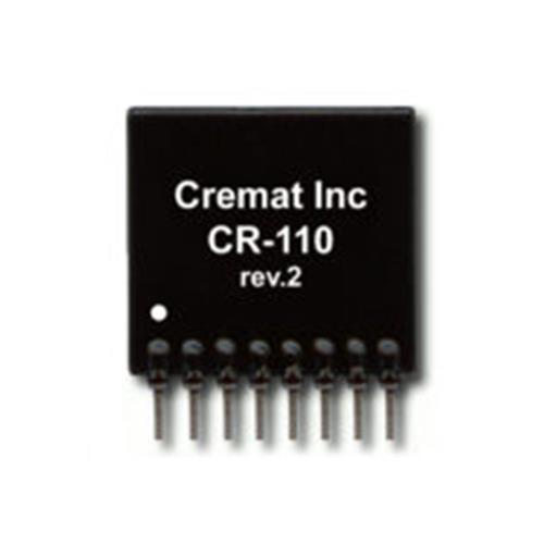
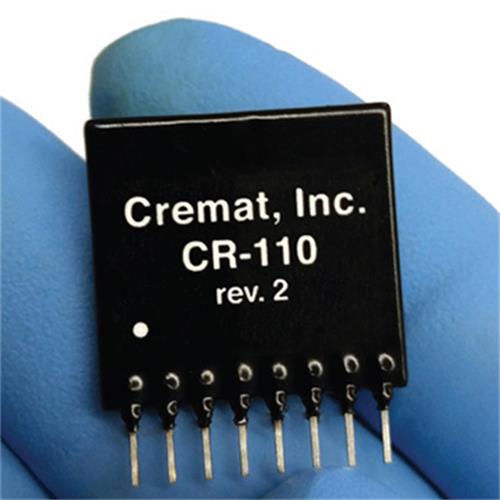
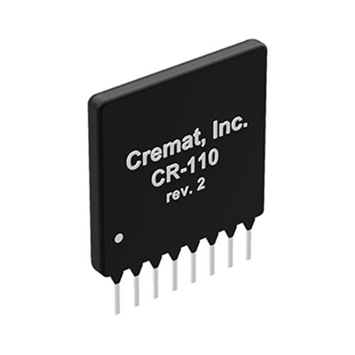
Package specification
The CR-110-R2 circuit is in an 8-pin SIP package (0.100" spacing). Pin 1 is marked with a white dot for identification.
Input and output waveforms
.png")
Preamplifier Specifications Assume temp =20 oC, Vs = 6.1V, unloaded output | |
Preamplification channels | 1 |
Equivalent noise charge (ENC)* ENC RMS |
200 electrons 0.03 femtoCoul. |
Equivalent noise in silicon | 1.7 keV (FWHM) |
Equivalent noise in CdZnTe | 2.4 keV (FWHM) |
ENC slope | 4 elect. RMS /pF |
Gain | 1.4 volts / pC 62 mV / MeV(Si) |
Rise time ** | 7 ns |
Decay time constant | 140μs |
Unsaturated output swing | -3 to +3 volts |
Maximum charge detectable per event | 1.3 x10⁷ electrons 2.1 pC |
Power supply voltage (Vs) Maximum minimum |
Vs = ±13 volts Vs = ±6 volts |
Power supply current (pos) (neg) | 7.5 mA 3.5 mA |
Power dissipation | 70 mW |
Operating temperature | -40 to +85 ℃ |
Output offset | +0.2 to -0.2 volts |
Output impedance | 50 ohms |
*Measured with input unconnected, using Gaussian shaping amplifier with time constant =1 μS. With a detector attached to the input, noise from the detector capacitance, leakage current, and dielectric losses will add to this figure. ** Pulse rise time (defined as the time to attain 90% of maximum value) has a linear relationship with input capacitance. Value cited in the table assumes zero added input capacitance. To calculate pulse rise time for practical situations, use the equation: tr =0.4 Cd + 7 ns, where tr is the pulse rise time in ns, and Cd is the added capacitance (e.g. detector capacitance) in pF. Others factors within the detection system may further limit this value. | |