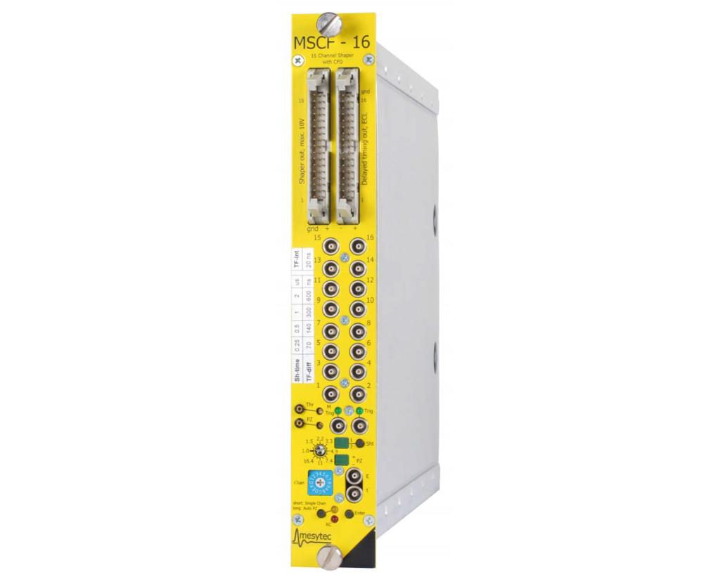
Mesytec MSCF-16-PMT is an integrating shaping / timing filter amplifier with constant fraction discriminator and multiplicity trigger. It provides 50 Ω terminated Lemo 00 inputs, and directly processes fast negative signals from PMTs or other charge sources.
Features:
• 16 channel NIM module, low power design
• Directly interfaces to anode signals from photo multipliers
• Shaping amplifiers with active baseline restorer
• Timing filter amplifiers
• CF discriminators (opt.: leading edge)
• ECL timing output with digital delay of 400 ns
• Trigger output
• Multiplicity trigger
• Remote control of discriminator thresholds, shaping time, gains and PZ
• 4 shaping times
• Gain adjustable from 100 pC to 20 nC for max range
• 50 Ω terminated Lemo 00 input.
• Low noise (0.2 pC rms / 2 pC rms)
• Mostly controllable via front panel
• Remote control via USB and mesytec control bus
• 4 selectable timing filter integration times
• ECL timing delay can be switched off
Technical Data
Input stage
• Gain adjust: gain can be set from 1 to 20 in 16 steps with factor 1.22 per step.
• Input connectors: 16x Lemo 00 series.
• Input termination 50 Ω, coded on the gain-polarity jumper.
• Gain jumpers with sensitivity 100pC~2nC and 1nC~20nC are standard.(Optional 50pC~1nC)
• Max allowed input offset: for 1nC jumper: ±5 mV, for 20nC jumper: ±100 mV.(direct PMT signals have no offset)
Shaper
• PZ is preadjusted and usually needs not to be user adjusted.
• 5th order Shaper (4th order for 0.12 us to 1 us type)
• Four shaping times selectable for groups of 4 channels
• Output amplitude: 0 to 10 V
• Active baseline restorer with settable threshold. (via RC only).
• DC-Offset with BLR: VDC ±5 mV, common offset adjust.
• Output connector: 34 pin male connector
• Integral non linearity <0.1 %
• Gain drift <0.01 % /°C
• Offset drift with BLR <50 V /°C
Noise
• For 1 nC jumper the noise is 0.1 pC rms
• For 2 nC jumper the noise is 0.2 pC rms
• For 20 nC it is 2 pC rms
Discriminator
• CFD or Leading edge (jumper selectable)
• CFD delays, and fraction selectable for groups of 4 channels
• CFD-Walk: for 30 ns (10 % to 90 %) input rise time, max ±1 ns (dynamic range 100:1)
• Threshold: adjustable, 0 % to 30 % of maximum range, in 256 steps.
Gate generator,Timing delay,ECL output
• Pulse width for trigger output: 400 ns
• Timing stop- ECL-Signals: delay 400 or 800 ns from trigger, width 200 ns
• Output connector: 34 pin male connector
Monitor output
• Output for timing filter signals
• Output for amplitude signals
• Selectable by rotary switch (Signal quality of monitor outputs may be slightly degraded compared to direct outputs.)
Multiplicity trigger
• Each channel above threshold contributes to multiplicity level, a multiplicity trigger is generated for: lower multiplicity threshold ≤ multiplicity level ≤ upper multiplicity threshold
• Coincidence interval adjustable from 20 ns up to 200 ns (default 75 ns).
• The multiplicity trigger is delayed by the coincidence time to the trigger signal.
• Multiplicities selectable via remote control
• Lower multiplicity threshold: 1 … 8, upper multiplicity threshold: 1 … 8 and ∞
• Multiplicity chaining: multiplicity outputs from several modules can be connected, resulting in a total multiplicity level of all connected modules. Multiplicity trigger windows of the connected modules act independently on the total multiplicity.
Power consumption: (max 9 W)
• +6 V 300 mA
• –6 V –700 mA
• +12 V 200 mA

