
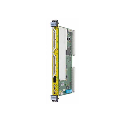
Mesytec MADC-32 is a fast and high quality 32 channels peak sensing ADC. It provides an 11 to 13 Bit (2 to 8 k) resolution with low differential non linearity due to sliding scale method. In 8 k mode it provides the high INL and resolution required for Ge detector readout. The conversion time is 800 ns for 32 channels at 2 k resolution. It supports zero suppression with individual thresholds.
Features
• High quality 11 to 13 bit (2, 4, 8 k) conversion with sliding scale ADC (DNL <1 % @ 4k).
• 800 ns, 1.6 us, 6.4 us conversion time for 32 channels wit 2 k, 4 k, 8 k resolution.
• 8 k (32 bit-)words multi event buffer (1 word corresponds to 1 converted channel => 240…2730 events total).
• Zero suppression with individual thresholds.
• Supports different types of time stamping.
• Independent bank operation.
• Two register adjustable gate generators are built in.
• Input range, register selectable 4 V, 8 V, 10 V.
• mesytec control bus to control external mesytec modules.
• Address modes: A24 / A32.
• Data transfer modes: D16 (registers), D32, BLT32, MBLT64, CBLT, CMBLT64.
• Multicast for event reset and time stamping start.
• Live insertion (can be inserted in a running crate).
New for V2.1 Revision:
• 8 k words memory.
• lower INL for very long shaping times and low amplitudes.
• Thresholds can be deactivated with a single register.
• Extended time stamp also for independent bank operation.
Technical Data
Input / Output Conversion input 1 kΩ, 4 V, 8 V or 10 V configurable via register Rise time min.: 50 ns, max: DC-conversion possible ECL inputs: standard ECL input, can be individually terminated via regi-ster setting NIM inputs: standard NIM NIM output: -0.7 V terminated mesytec control bus output, shares connector with busy output. +0.7 V terminated. Power consumption (Total: 4.0 W) +5 V, + 190 mA +12 V, + 160 mA –12 V, – 80 mA Conversion, busy time Digital conversion time: 800 ns for 32 channels @ 2 k resolution Conversion starts 50 ns after gates closes Recovery time after conversion: 200 ns | | Lemo and ECL inputs Minimum gate width: 80 ns Minimum clear signals: 50 ns Maximum external reference oscillator frequency: 75 MHz
Gate generators Two gate generators are provided for each bank of 16 channels. When the gate generators are used, the gate inputs work as trigger inputs to start the gate generators. When active the gate generators create a gate for the stretchers. Delays and widths can be adjusted independently in steps of 50 ns. Minimum delay (gate_delay parameter = 0) is 25 ns. For monitoring, the gate signals can be switched to the busy output via register setting. |